FBX (limb) rotation values
 lencsev
Posts: 9
lencsev
Posts: 9
I get different limb rotation values in programs like Blender or Unity3D than DAZ values when I import a model from DAZ3D fbx.
For example:
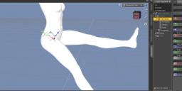
I set the G3F's right thigh's bend to -45 degrees in DAZ3D (see attachment1) and I export the model as fbx (traditional way, no bridge).
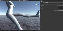
When I import this fbx into Unity, everything seems OK, the position looks the same as in Daz3D (see attachment2), but the right thigh's rotation values are now different: [-44.686, -3.937, 5.713]
I would like to know how is this calculated from -45 degrees and why. I guess it's connected to bone orientations/rotation orders somehow, but I had no success finding it out.
Here is the limbNode from the fbx file:
Model: 4093523728, "Model::rThighBend", "LimbNode" {
Version: 232
Properties70: {
P: "RotationOffset", "Vector3D", "Vector", "",-7.90920782089233,-10.6266784667969,-1.48210310935974
P: "RotationOrder", "enum", "", "",2
P: "PreRotation", "Vector3D", "Vector", "",0.648822605609894,-4.95046615600586,-1.92385697364807
P: "PostRotation", "Vector3D", "Vector", "",0.648822605609894,-4.95046615600586,-1.92385697364807
P: "RotationActive", "bool", "", "",1
P: "RotationMin", "Vector3D", "Vector", "",-115,0,-85
P: "RotationMax", "Vector3D", "Vector", "",35,0,20
P: "RotationMinX", "bool", "", "",1
P: "RotationMinY", "bool", "", "",1
P: "RotationMinZ", "bool", "", "",1
P: "RotationMaxX", "bool", "", "",1
P: "RotationMaxY", "bool", "", "",1
P: "RotationMaxZ", "bool", "", "",1
P: "InheritType", "enum", "", "",2
P: "ScalingMax", "Vector3D", "Vector", "",0,0,0
P: "DefaultAttributeIndex", "int", "Integer", "",0
P: "Lcl Rotation", "Lcl Rotation", "", "A",-45,0,0
}
Daz 3D is part of 
Connect
DAZ Productions, Inc.
7533 S Center View Ct #4664
West Jordan, UT 84084
Licensing Agreement | Terms of Service | Privacy Policy | EULA
© 2025 Daz Productions Inc. All Rights Reserved.
Comments
Wouldn't we all. But I think you're right... it's probably the orientation.
I've been playing around in the Joint Editor a lot lately, just trying to figure out how it all works. I think the rotations come out wrong because when you apply rotations to a bone, these rotations are with respect to its orientation axes, not it's parent's axes. I think FBX doesn't understand that, or hasn't been told that.
I think a bone starts out along the world axis of the first axis of its rotation order, and then the orientation is applied in XYZ order, regardless of the bone's rotation order, to arrive at the axes about which the bone (and its children) will be rotated. So if a bone has an orientation that is not [0,0,0], then those axes will not be the same as the bone's parent's axes.
You probably already know this, but it seems that bone orientation is a way to allow the artists and riggers to tweak the way an armature deforms at every joint, probably why Daz characters deform so beautifully. Worth the extra matrix multiplications.
Disclaimer: At this point, I could still be totally wrong, but the above seems to jibe with everything I see in the Joint Editor. If you discover anything or can contradict me, please share :)
Thanks for your reply.
Yeah, I guess you are right, the imported model's bones are all lookin at the same direction. So it's quite possible that the rotation order is simply ignored in 3rd party software. However, it doesn't explain why a one component rotation comes out differently. I mean if the to other components are zero, like X:-45, Y:0, Z:0, the order shouldn't really matter. It feels like some kind of rotation compensation on the importers side, considering I do not see the 'final' (-44.686, -3.937, 5.713) euler angles anywhere in the fbx, only the original one (P: "Lcl Rotation", "Lcl Rotation", "", "A",-45,0,0).
The only thing that I can think of is that Daz reckons the rotations with respect to the bone's oriented axes, while other software reckons it with respect to just the parent bone's axes. The RightThighBend bone does have a small, but non-zero orientation.
I dunno... my own understanding is dawning pretty slowly and I keep finding contradictory evidence all the time.
Well, I did some experiments. Exporting the model in a different format (collada/dae) shed some light upon the calculations of the final angles in Unity. The rThighBend looks like this in dae with a -45 deg. bend rotation:
<node id="rThighBend" name="rThighBend" sid="rThighBend" type="JOINT">
<translate>-7.909207821 -10.62667847 -1.482103109</translate>
<rotate sid="rotateX">1 0 0 -44.89788437</rotate>
<rotate sid="rotateZ">0 0 1 -2.938573837</rotate>
<rotate sid="rotateY">0 1 0 2.801780939</rotate>
<scale>1 1 1</scale>
If I rotate the limb described in the dae file (XZY rotation order) with the values above in Unity, like:
if (bone.name == "rThighBend")
{
bone.Rotate(-44.89788437f, 0, 0);
bone.Rotate(0, 0, 2.938573837f);
bone.Rotate(0, -2.801780939f, 0);
}
I get the [-44.686, -3.937, 5.713] values which are the numbers I was originally looking for. But the question remains as I still missing a step reproducing the X-Z-Y rotation components.
The red highlights are what make me think its still orientation that's making the difference. Those axes are of the world frame, not rThighBend's slightly rotated axes because of its small but non-zero orientation. I think your export method is accounting for orientation, and so the numbers are slightly different. That you rotated just on x, but yet y and z rotation also changed kind of makes sense: the rotation was not around world x, but around the bone's oriented x. My hypothesis would be more likely if you did the experiment with a bone that had a greater orientation, and the discrepancy also grew.
I hate that no one at Daz will just tell us how this works. It would take mere minutes for someone to type an explanation.
It could also be that your export method and Daz use different Euler Angle conventions... one rotates the axes as the rotations are applied, while the other leaves the axes in place. The bad thing is that both methods are capable of representing all possible rotations, and so no one is better than the other in an absolute sense. I don't know, I'm guessing.
Agreed, absolutely. I simply do not have more time for this project, when I asked I thought it's a simple question that would be answered in minutes, and it's not some kind of search for the holy grail
I share my conclusion, after a lot of trial&error testing: I'm pretty sure that applying the pre/post rotations are the key to generate similar results as the fbx importer (those values are in the fbx file). But the order is VERY tricky, seems to change from limb to limb, and even the pre/main/post order is not consistent.
Anyway, TheMysteryIsThePoint, thanks for your input!
I am sorry I can only comiserate... thanks for sharing your experiments.