First WIP - rapier
Hello!
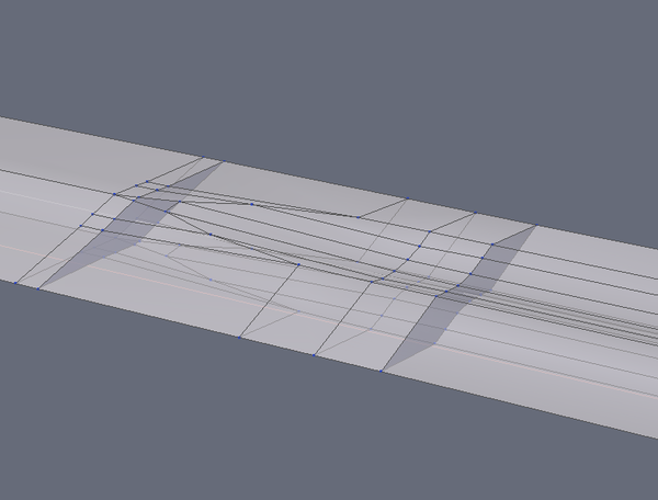
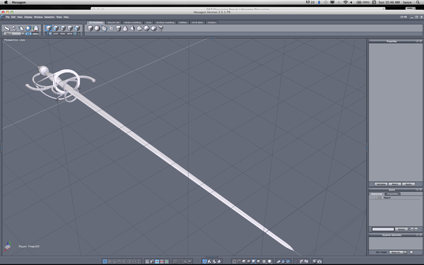
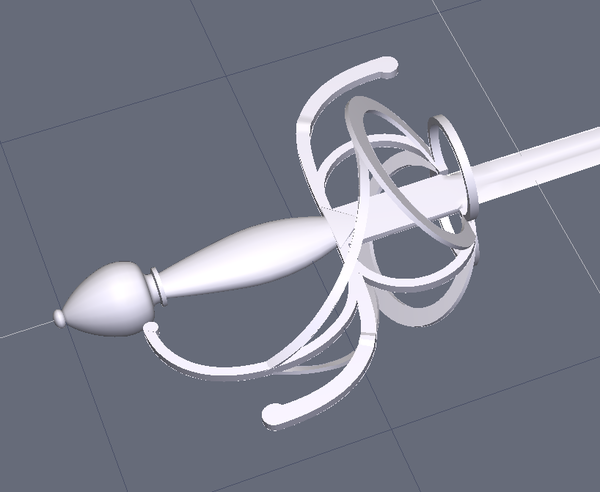
These are a couple of screenshots of my first Hex 2.5 model, and I know I made some rookie errors. How do I get rid of some of the interior "leftovers" from where I welded two constructs together? For example, there is a cross section surface inside the blade, as shown in the screenshot.
Thanks!


Rapier_Fuller_Transition.png
785 x 596 - 84K


Rapier_WIP_1.png
1920 x 1200 - 328K


Rapier_WIP_2_w:lines.png
812 x 674 - 114K


Rapier_WIP_2.png
818 x 671 - 96K
Post edited by lexbaird on


Comments
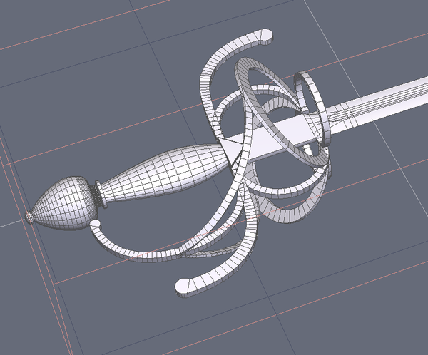
Follow up question: Apparently "n-gons" (shapes with more than 4 points) are problems? At the tips of the knucklebow and quillons, there are partial cylinders, which means the flat round parts have more than 4 points around the perimeter. Should I try to fix that?
Short answer...YES!
Somewhat longer answer...any smoothing or subdivision applied to the surface will turn it very ugly, at the least, if it just doesn't break the mesh.
Nice sword lexbaird. I see what has gone wrong, when you bridged the two sections together you did it by bridging the faces rather than the lines, this left the original face behind. To fix the problem select a face above the unwanted face and use the hide faces option (bottom right of Hex you have 2 spheres, one has been cut in half - 3rd box from the right), simply hide the face and delete the unwanted one.
As for your second problem, delete the top face, then bridge the lines which are opposite each other, going by your picture above start at the widest part and work your way up bridging each set of edges one at a time (you could do more than one, but best to be on the safe side).
Oh, the part known as the blood groove needs a couple more tesselations, one on each side of the shaped bit, so it will keep it shape (the same goes for the cutting edge).
I like the look of your sword, please post some images when you have finished it :)
Thanks for the advice, and I'll post it up when done. It will probably end up a freebie someplace, as a bit of payback for the generosity of other modelers!
Actually, I didn't use face bridging. I built the sections, and then capped the ends of the extrusions. That apparently was where I went wrong. I cant delete the capped ends! I have tried picking them with the face tool and deleting, but no go. The only successful method seems to be picking all the other faces and doing a copy/paste.
Anyway, I ended up rebuilding the blade from fresh extrusions and using proximity weld to join the parts. I'll need to rework the hilt in the same way, unless I can figure out how to get the !@#% end caps to delete.
Odd. There's no reason why they shouldn't delete....unless...
...you have a quirk on your system like I have on mine.
Try this: Select the endcaps and instead of hitting your delete key, hit CTL-X.
If that works, then you can go into the "shortcut editor" go to the "edit" tab and look for "Delete". The associated default key is, of course, "Del".
On my system, I had to TELL it my delete key was my delete key by selecting the button and hitting my delete key. When I did that, the "Del" was replaced by a little box that typically represents a non-displayable character.
Bizarre it may be, but now my delete key works to delete things. :)
Or, if you're using a MAC, use Command-X instead of Ctl-X.
Thanks, and I am on a Mac. I figured out the Cmd-X workaround when I did a copy/paste on another part. I'll try the shortcut editor trick.
New questions for this project!
The ultimate goal is a usable prop for Daz Studio or Poser.
Before I go to a lot of work combining two objects into a single one, is it necessary? For example, a cube with a cylinder thrust thru it. Rather than punch holes and weld the objects, will anything distressing happen if I just leave them as separate discrete but grouped objects? I am thinking specifically of the blade and hilt.
Second, I was able to make 99.9% of my hilt mesh into quad shapes, with two tiny hidden triangular holes in the mesh. Leave them as holes, or fill them? Can I mix triangles and quads? I gather that the quad restriction relates to the smoothing subdivision, and this will be smoothed very minimally, if at all.
If I resolve these issues, I think this is ready for surface and paint, followed by rigging in D/S to have the blade flexible. If that all works, I'll do a matching dagger, scabbard and belt rig.
lexbaird:
Looks good for a first mesh. There are a few things I would fix, and a few modeling techniques I would employ if this was my model, but you are off to a good start.
I've been following this, but was hesitant to comment. I was going to wait to see what others would write regarding your last post above, but what the hell, I'm taking a break from working, so...
There are different ways to model, so I will just offer my opinions, and the style I've come to settle on. Others might offer you different solutions:
1. I was wondering if you were building this for DS/Poser, and since you have confirmed this you might want to look into techniques that will help your mesh look it's best in DS/Poser for hard edged models. I use final mesh mechanical bevels (opposed to pre-smooth mechanical beveling technique). This, of course, is also dependent on if you will employ in-software Sub-d (DS), or not.
2. I don't believe you need to vertex weld all your work together. I use to do this, but now I "combine/group" separate meshes at coincident location to form the complete model, including limited "poke through" mesh into mesh. I find this dependent on the mesh, and generally do not allow culled facets inside of other facets. Exceptions, for me, would be sword blade slightly inside of guard if I am not employing coincident vertex placement to avoid any gaps.
3. Quads, quads, quads... That's all we ever hear. No, your mesh does not have to be all quads, but you should strive for (mostly) quads with good topology. Hint... If you have a well designed cage with purposeful triangles with one sub-d iteration in mind, you will get all clean quad loops. I employ this technique a lot when I am not completely hand cutting the entire mesh to completion. I leave tris as is where they are needed, or only recourse to quad conversion yields another complete quad loop.
Hidden triangles?
Not sure exactly what you mean, but if you are saying you have two triangle shaped holes/gaps, I would suggest you fill them in with facets.
If they are hidden within the mesh, there is bad topology going on. If they are clearly visible, you might get artifacting in DS/Poser.
Yes, you can mix triangles and quads. You just want to avoid elongated tris, n-gons, and certain quads (inverse tangents, parallel edges, non-coplanar, etc.) which yield arifacts.
4. I wouldn't rig your sword in order to have a flexible blade. You should keep it as a prop, and create a morph target to flex the blade. One MT should do it utilizing both positive, and negative attributes. To create, just select all verts of the blade you wish affected, and then give it a bend on one plane from strong-to-weak/tip-to-base. Save the MT, and apply in software. Dial positive to flex in one direction, and negative to flex in the opposite direction.
Good luck...
Thanks! Sounds like I am on the right track. Due to the weird intersecting tri-ring area, I ended up with vertices not quite totalling up evenly, and thus two small triangular holes hidden under the rings. I'll just fill them.
Good ideal with the morph target for a bend! Now, I have to figure out how....
Also, I only have the vaguest idea what "sub-D", pre-smoothing, and mechanical beveling mean yet. This model has some rounded edges done as actual vertices, and everything looks pretty good without any smoothing (smoothing level 0). I'm thinking I'll leave it there. Is there a way to use smoothing on only part of a model, like the hilt, but not the blade?
Currently, I'm messing with UVs.
I'm attaching progress pics, including the complex intersection under the rings, and where the blade section just dives into the triangular hilt buffer.
Lavoro molto preciso.
Bravo.
Bye
Test render done in D/S. No bump maps yet.
Looking good, lexbaird.
Looking good Lexbaird.
Did you get my last PM ?
John,
I did get it, thanks. Doing the UV for the hilt was a trial! Anyway, thanks for the help, encouragement and advice from all. Here is a render with a bump mapped texture on the ironwork and grip.
I think I'll call this one done, and work on some companion pieces, maybe a dagger, plus scabbard and belt hanger. When I get the set done, I'll contribute it someplace!
Lex
Finished set at:
http://www.ShareCG.com/v/67399/view/5/3D-Model/Renaissance-Rapier-and-Dagger